Español
 Francés
 Deutsch
 Русский
 العربية
 Português
 日本語
日本語
 한국어
한국어
 Italiano


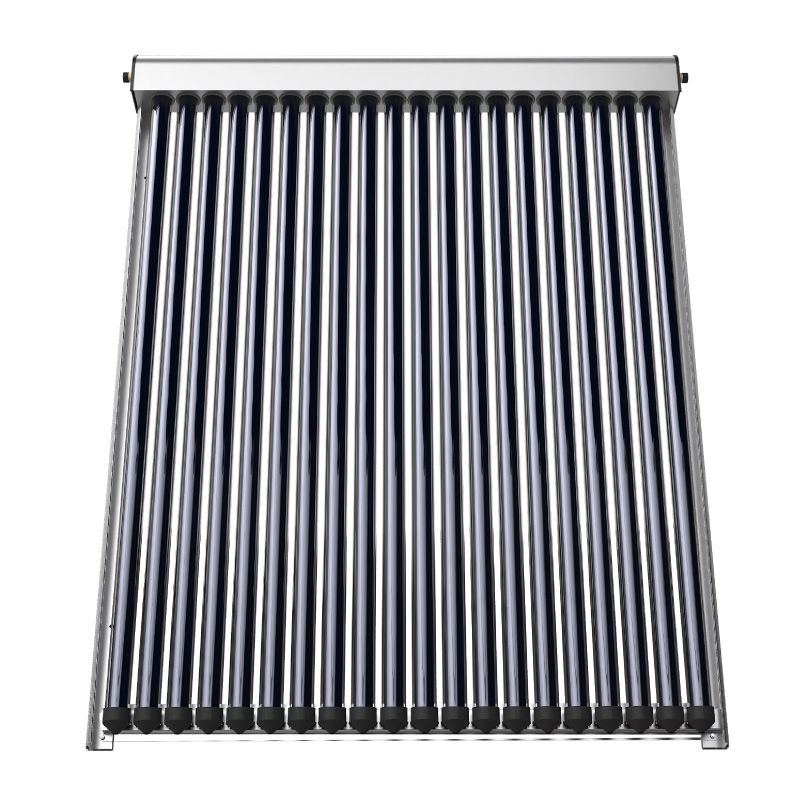

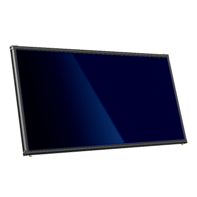
U-Tube Evacuated Tube Solar Collector
High heat exchange efficiency:Metal material ensures fast heat conduction; vacuum layer minimizes heat loss.
Stable pressure operation:Compatible with municipal water supply, no water temperature fluctuation or water hammer issues, suitable for both residential and commercial use.
Freeze-proof & weather-resistant:Separated heat absorber and working fluid pipeline prevents freezing in low temperatures, ideal for northern regions.
Low maintenance cost:Robust structure resists impacts; only regular cleaning is needed with low failure rate.
Flexible capacity expansion:Heating power can be adjusted by increasing or decreasing the number of evacuated tubes.
Product Definition & Core Structure
The U-Tube Solar Collector is a pressurized solar thermal collector designed for stable, long-term heat generation in centralized systems. Unlike direct-flow vacuum tube collectors, the U-tube design separates the heat transfer circuit from domestic water circulation, allowing solar energy to be absorbed efficiently while maintaining high operational safety.
The core structure consists of U-shaped metal flow channels, evacuated glass tubes, high-conductivity aluminum fins, and an integrated manifold. Solar radiation passes through the outer glass layer of the vacuum tube and is absorbed by the internal fin structure. Heat is then transferred to the U-shaped tube via direct metal contact, where a dedicated heat transfer medium circulates and carries thermal energy to the system side.
This indirect heat transfer mechanism enables the collector to operate under pressure, eliminates water stagnation inside the tubes, and provides higher reliability compared to traditional water-in-tube designs. As a result, the U-tube collector is particularly suitable for engineering projects that require continuous, stable heat output rather than intermittent domestic use.
In centralized solar thermal systems, the U-tube collector typically serves as the primary heat source or a stable supplementary heat source, working in coordination with buffer tanks, heat exchangers, and auxiliary heating equipment.

Application Scenarios
The U-Tube Solar Collector is engineered for a wide range of thermal demand scenarios, particularly where system stability, safety, and long service life are prioritized.
In residential applications, the collector is commonly used in centralized domestic hot water systems for apartment complexes and residential communities. Its pressurized design allows integration with modern building plumbing systems, ensuring consistent hot water supply without the risks associated with freezing or tube rupture.
For commercial buildings such as hotels, schools, hospitals, and recreational facilities, hot water demand is continuous and predictable. The U-tube collector’s stable output and low maintenance requirements make it well-suited for these environments, where downtime or frequent servicing would directly affect daily operations.
In industrial parks and industrial heating systems, the collector can be used for process water preheating, space heating, or as part of a hybrid thermal system. The use of glycol-based heat transfer fluids allows reliable operation in low-temperature regions, making it particularly advantageous in northern and cold-climate areas.
Overall, the U-tube collector is best applied in projects that emphasize long-term reliability, centralized management, and predictable thermal demand rather than small, decentralized household systems.
Key Advantages
Safe and Stable Operation
One of the most significant advantages of the U-tube solar collector lies in its operational safety. The system supports pressurized operation while ensuring that no water flows directly inside the vacuum tubes. This design fundamentally eliminates common failure risks such as tube bursting caused by overheating in summer or freezing damage during winter.
Since the heat transfer medium circulates inside a sealed metal flow channel, the collector remains unaffected by water quality issues. Scaling, leakage, and internal corrosion—typical problems in water-based collectors—are effectively avoided. This not only improves safety but also significantly reduces long-term maintenance frequency.
High Heat Transfer Efficiency
The collector adopts a secondary heat exchange design based on U-shaped metal channels. Heat absorbed by the fin structure is rapidly conducted to the heat transfer fluid through high-conductivity materials. This configuration shortens heat transfer paths and improves overall thermal response speed.
Compared with conventional designs, the U-tube structure maintains stable efficiency across varying operating conditions, making it suitable for projects that require consistent heat output rather than rapid start-stop cycles.
Durability and Corrosion Resistance
All heat transfer components are enclosed within a sealed flow channel, isolating them from external environmental factors. Copper and selected rare-earth alloy materials provide excellent corrosion resistance and thermal stability. Combined with high-toughness welding processes, the collector is designed to withstand long-term thermal cycling and continuous operation.
This structural durability directly translates into longer service life and reduced risk of unexpected system failures.
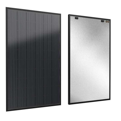
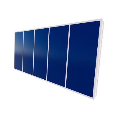
Customizable Design and Architectural Integration
The collector can be customized in terms of dimensions and configuration to meet specific project requirements. Its modular design allows flexible layout within solar arrays, while the GM aluminum alloy frame provides high structural strength and ease of installation.
The brushed silver finish supports architectural integration, making the collector suitable for projects where visual consistency with building design is required.
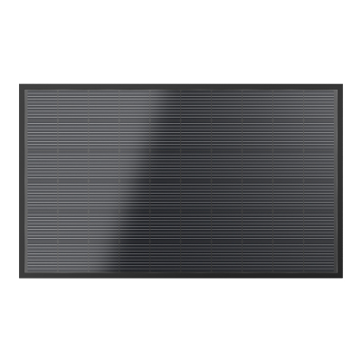
Component & Material Advantages
The fin structure is manufactured from 3003 anti-rust aluminum, a material known for its stable performance under prolonged sun exposure. Its high thermal conductivity ensures efficient heat absorption and transfer, even under fluctuating ambient conditions.
The flow channel is primarily constructed from copper, selected for its excellent thermal conductivity and corrosion resistance. In selected models, rare-earth alloy tubes are used to further enhance oxidation resistance and long-term stability, particularly in demanding environments.
The welding process employs silver-copper welding rods, which preserve joint strength and flexibility. This approach minimizes the risk of weld fatigue, cracking, or corrosion over extended operating periods.
The heat transfer medium can be selected according to ambient temperature conditions. This flexibility ensures stable circulation and heat transfer efficiency across different climatic zones.
Technical Specifications
| Collector Model | U-tube318 | U-tube395 | U-tube472 |
| Dimensions (mm) | 1720×1936×156 | 2120×1936×156 | 2520×1936×156 |
| Vacuum Tube Size | φ58×1800 | φ58×1800 | φ58×1800 |
| Number of Tubes | 20 | 25 | 30 |
| Total Area (m²) | 3.18 | 3.95 | 4.72 |
| Absorber Area (m²) | 2 | 2.5 | 3 |
| Net Weight (kg) | 67 | 86 | 102 |
| Working Pressure (MPa) | 1 | 1 | 1 |
| Connector Size | G3/4" Thread | G3/4" Thread | G3/4" Thread |
| Number of Connectors | 2 | 2 | 2 |
| Total Heat Loss Coefficient | 2.252 W/(m²·K) | 2.252 W/(m²·K) | 2.252 W/(m²·K) |
| Max Working Temperature (°C) | 120 | 120 | 120 |
| Peak Efficiency | 0.701 | 0.701 | 0.701 |
| Rated Efficiency | 0.59 | 0.59 | 0.59 |
| Rated Output @400 W/m² (kW) | 0.34 | 0.42 | 0.5 |
| Rated Output @700 W/m² (kW) | 0.76 | 0.95 | 1.62 |
| Rated Output @1000 W/m² (kW) | 1.18 | 1.47 | 1.77 |
| Water Tank Capacity (L) | 3.84 | 4.8 | 5.75 |
U-Tube vs. Heat Pipe Collectors
From an engineering perspective, the U-tube collector occupies a balanced position between heat pipe collectors and traditional vacuum tube systems.
Heat pipe collectors offer fast thermal response and strong low-temperature performance but may face long-term reliability risks if the internal working fluid degrades. Traditional vacuum tube collectors provide low initial cost but suffer from higher maintenance frequency and lower system reliability.
The U-tube collector prioritizes system stability, low maintenance, and long-term operational safety, making it a practical choice for large-scale and long-life projects.
| Aspect | U-Tube Collector | Heat Pipe Collector | Traditional Vacuum Tube |
| Efficiency | Stable, moderate performance | High, fast start-up | High initially, degrades over time |
| Anti-freeze | Excellent (glycol circulation) | Good (sealed heat pipe) | Weak |
| System Reliability | High | Medium | Low |
| Maintenance Cost | Low | Medium | Medium-High |
| Installation Flexibility | Medium | High | Low |
| Cost Performance | Medium-High | Medium | High |
| Typical Applications | Cold regions, large systems | Cold regions, fast response systems | Warm regions, residential use |
Why Choose Soletks Solar
Soletks Solar provides U-tube collectors as an original manufacturer with full customization capability. Six production bases and a vertically integrated supply chain ensure reliable delivery capacity and consistent product quality.
Each collector undergoes more than 60 quality inspection procedures, supported by AI-based quality control systems. With 117 patented technologies and a comprehensive system design capability, Soletks Solar supports projects from component selection to complete system integration.
With over 20 years of experience in clean thermal energy applications, Soletks Solar has delivered solutions across building heating, industrial thermal systems, agricultural drying, and extreme climate regions.