Chinese
 Español
 Francés
 Deutsch
 Русский
 العربية
 Português
 日本語
 한국어
 Italiano

Solar Air Heater Efficiency 40% to 70%: What the Number Really Means
Solar Air Heater Efficiency 40% to 70%: What the Number Really Means
A high outlet temperature does not prove high efficiency. Useful heat = airflow × ΔT. This page shows the math, the worked examples and why outlet temperature alone misleads buyers.
This article is the engineering performance and efficiency math page for solar air heaters. For a broader product walkthrough (system types, applications, supplier selection, advantages and limitations), see our Solar Air Heater B2B Guide. For greenhouse-specific design discussion, see our Solar Air Collector for Greenhouse Heating engineering guide. This page focuses on how to calculate the efficiency number, why outlet temperature alone is misleading, and what airflow × ΔT actually delivers.
Short Answer
Quick Verdict
Solar air heater efficiency is useful heat delivered to moving air divided by solar power falling on the collector aperture. A typical practical range of 40% to 70% is realistic only when airflow (m³/h), temperature rise (°C), aperture area (m²) and irradiance (W/m²) are stated together.
A high outlet temperature does not prove high efficiency. A collector delivering 70 °C air at 100 m³/h produces about 1.51 kW of useful heat, while the same collector at 25 °C rise and 300 m³/h delivers 2.51 kW — the lower outlet temperature actually transports more heat. For design, calculate useful heat output first, then calculate efficiency. The Soletks AFPC flat plate solar air collector is rated at peak efficiency ~0.70 with a recommended 150 m³/h airflow and 100 Pa static pressure per module under reference test conditions.[1]
For Soletks air-heating paths, compare the solar air collector category, the DVC500 solar air collector, the APVT-590 air-based PVT module, the solar air heater B2B guide, and the Soletks contact page.

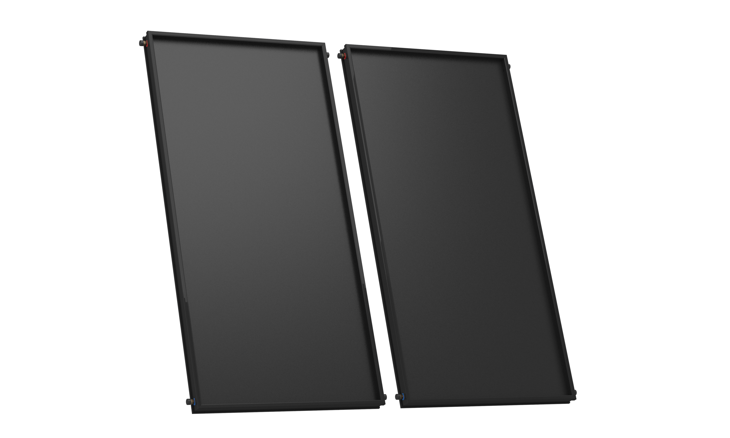
Reference module
AFPC belongs beside the airflow and pressure numbers that make the efficiency claim reproducible.
The useful spec is not the product image by itself; it is the operating point: peak efficiency, module airflow, static pressure and aperture area.
Key Takeaways
What controls the real number
Efficiency formula: η = (airflow × ΔT × 0.000335) ÷ (aperture area × irradiance ÷ 1000), where 0.000335 is ρ × cp / 3600 ≈ 1.2 × 1.005 / 3600 in kW/(m³/h · °C) at ~20 °C.[2]
Outlet temperature alone is misleading. Useful heat = airflow × ΔT, so the same collector can read "60 °C outlet" and deliver either 1.5 kW or 3.0 kW depending on fan speed.
Reference AFPC product values: 1.87 m² aperture, peak efficiency ~0.70, 100 Pa static pressure, 150 m³/h airflow per module, up to 26 modules in series.[1]
Application efficiency targets vary: 45–65% for drying, 50–70% for greenhouse and warehouse preheat, 40–60% for fresh-air preheat, 20–50% thermal for air-based PVT (plus PV output).
ISO 9806:2017 (and the newer EN ISO 9806:2025) define test procedures for air collectors, including air leakage requirements.[3]
Buyer rule: reject any efficiency claim that does not state airflow, ΔT, irradiance and aperture area together.
How This Differs from Our B2B Guide
To avoid duplicating our Solar Air Heater B2B Guide, the two articles cover different decisions:
This article — efficiency math
B2B Guide — product walkthrough
Buyers evaluating a real project should read both.
The Efficiency Formula
Solar air heater efficiency compares useful heat transferred to the air with solar input on the collector aperture. The formula requires four inputs: airflow, temperature rise, collector aperture area and irradiance.
Core efficiency equations
Useful heat output (kW)
  = airflow (m³/h) × temperature rise (°C) × 0.000335

Solar input (kW)
  = aperture area (m²) × irradiance (W/m²) ÷ 1000

Efficiency (%)
  = useful heat output ÷ solar input × 100
Where does 0.000335 come from? It is the volumetric heat capacity of air converted to consistent units:
ρ_air × cp_air ÷ 3600
= 1.2 kg/m³ × 1.005 kJ/(kg·°C) ÷ 3600 s/h
≈ 0.000335 kW·h/(m³·°C)
This treats air at roughly 20 °C and atmospheric pressure. At higher altitude or much higher operating temperature, ρ drops slightly and the factor is closer to ~0.0003 — for screening purposes, 0.000335 is the standard HVAC sensible-heat constant.[2]
Worked snippet: at 300 m³/h and 25 °C temperature rise, useful heat output is 300 × 25 × 0.000335 = 2.51 kW. The buyer should always request both airflow and ΔT — outlet temperature alone is not sufficient.
Worked Example: 5 m² Collector
A 5 m² solar air heater can look efficient or weak depending on airflow and temperature rise. The same collector area produces very different useful heat numbers when fan speed changes.
Source note. Values below are screening assumptions for explanation. Final design should use product test data (e.g., the Soletks AFPC datasheet specifies 150 m³/h airflow per 1.87 m² module at ~100 Pa static pressure)[1], measured airflow at the project, and site irradiation from NASA POWER or PVGIS.
Calculation
Solar input  = 5 × 800 ÷ 1000           = 4.0  kW
Useful heat  = 300 × 25 × 0.000335      = 2.51 kW
Efficiency   = 2.51 ÷ 4.0 × 100         = 62.8 %
Recommendation. A 62.8% operating point is a reasonable mid-range result because both useful heat output and airflow are documented. A claim of "70 °C outlet temperature" without airflow tells the buyer nothing about useful heat. The next section shows why.
Why Outlet Temperature Alone Misleads
Outlet temperature is one of two factors in useful heat output. Heat output rises when airflow and temperature rise work together; either one alone can be tuned without improving real performance.
Source note. Examples below use the same heat-output formula at 4.0 kW solar input (5 m² × 800 W/m²), so the comparison isolates airflow versus ΔT. The 0.000335 factor is the standard HVAC sensible-heat constant for air.[2]
Useful heat by airflow setting (5 m², 800 W/m²)
Bars show useful heat output (kW). The teal bar is the best practical operating zone — more heat at a lower, safer outlet temperature.
| Airflow | ΔT | Outlet (20 °C inlet) | Useful heat | Efficiency | What the buyer learns |
|---|---|---|---|---|---|
| 100 m³/h | 45 °C | 65 °C | 1.51 kW | 37.7% | High temperature but low total heat — common in low-airflow drying claims |
| 300 m³/h | 25 °C | 45 °C | 2.51 kW | 62.8% | Lower temperature but more useful heat — best practical zone |
| 500 m³/h | 18 °C | 38 °C | 3.02 kW | 75.4% | Even more useful heat at lower outlet temperature |
| 800 m³/h | 10 °C | 30 °C | 2.68 kW | 67.0% | Very high airflow erodes ΔT and total useful heat |
The mechanism: at low airflow, the absorber overheats, so back losses and re-radiation rise — the air leaves hot but the collector wastes more energy to ambient. At very high airflow, ΔT collapses because the residence time is too short. The best design point is the airflow at which the application's temperature requirement is just met, not the highest possible outlet temperature.
This is the single most common confusion in solar air heater procurement: a supplier quotes "outlet 70 °C" without disclosing that this requires 80 m³/h — which then cannot dry a real product batch in useful time. Always request the airflow curve.
 Conformity file
Certification plus operating data
The certificate tells you the product family is auditable; the airflow curve tells you whether the efficiency claim is useful.
This document belongs next to the airflow and pressure-drop table, not as a full-height page image. For solar air heaters, buyers should read conformity evidence together with delivered airflow, delta-T and fan operating point.
Open full certificateTypical Efficiency Ranges by Condition
A 40% to 70% efficiency range is credible only when operating conditions are clear. Air collectors are particularly sensitive to airflow, inlet temperature, absorber design, insulation, glazing condition, sealing quality and wind.
Source note. Bands below are practical screening ranges for buyer comparison. Request product-specific ISO 9806 test data (or equivalent measurement) before procurement.[3]
| Operating condition | Practical efficiency range | Design interpretation |
|---|---|---|
| Low airflow, high outlet temperature | 35–55% | Absorber overheats, back losses dominate |
| Balanced airflow and useful ΔT | 50–70% | Best design zone for drying and preheat |
| Very high airflow, low ΔT | 40–60% | Useful for ventilation preheat, weak for drying |
| Cold windy outdoor condition | 30–55% | Heat loss rises through glazing and frame edges |
| Air-based PVT warm-air recovery | 20–50% thermal (+ PV) | Value both electricity and heat together |
| Transpired (unglazed) collector | 50–75% on preheat | High airflow, low ΔT, ventilation-only use |
For drying, greenhouse or workshop applications, the correct efficiency target is not the highest number. The correct target is the useful heat delivered at the temperature, humidity and airflow the process actually accepts.
Efficiency by Application
The best operating point changes by application because each load needs a different temperature, airflow and operating schedule.
Source note. Application bands below are screening ranges for RFQ planning and require product confirmation against the supplier datasheet.[1]
| Application | Useful outlet range | Airflow priority | Practical efficiency target |
|---|---|---|---|
| Herb / food drying | 45–70 °C | Medium airflow with humidity control | 45–65% |
| Greenhouse heating | 25–45 °C | High airflow during cold morning hours | 50–70% |
| Warehouse / workshop preheat | 20–40 °C | High airflow with full-area circulation | 45–65% |
| Fresh-air ventilation preheat | 15–35 °C | High airflow, low pressure drop | 40–60% |
| Timber / lumber drying | 40–60 °C | Steady airflow over many hours | 45–60% |
| Air-based PVT heat recovery | 25–50 °C | Matched to duct pressure | 20–50% thermal (+ PV) |
For multi-module systems, remember that the Soletks AFPC product engineering note specifies 3,550 m³/h of fan airflow per m² of collector area for large arrays, with fan temperature resistance 150 °C on the exhaust side or 70 °C on the inlet side, and minimum fan static pressure above 300 Pa when more than two collectors are connected in series.[1] These constraints often decide whether the "70%" lab efficiency can be reproduced in the field.
Engineering array context
Large arrays prove field efficiency through fan pressure and module-series limits, not brochure peak numbers.
For multi-module systems, static pressure above 300 Pa, fan temperature rating and series count decide whether lab efficiency can be reproduced on site.
ISO 9806 Air Collector Testing
A serious solar air heater proposal should state performance under a recognized test method. ISO 9806:2017 — and the newer EN ISO 9806:2025 — define test procedures for fluid heating solar collectors, including air collectors, covering thermal performance, durability, reliability, safety and (importantly for air collectors) air leakage testing.[3]
Air collector performance is described by the same general efficiency curve form as liquid collectors:
η = η0 − a1 × (Tm − Ta) / G − a2 × (Tm − Ta)² / G
where η0 is the optical (zero-loss) efficiency, a1 and a2 are heat-loss coefficients, Tm is mean fluid (air) temperature, Ta is ambient temperature and G is irradiance. Crucially for air collectors, η0 and the coefficients depend on the test airflow rate — so the test report must state the mass flow or volume flow used during testing. Two collectors with the same η0 but different test airflows are not directly comparable.
Standards and Documents to Request
A solar air heater proposal should provide performance data, airflow conditions and electrical control documentation.
| Standard or document | Applies to | Buyer action |
|---|---|---|
| ISO 9806:2017 / EN ISO 9806:2025 | Solar collector performance testing, including air collectors | Request η curve with stated test airflow |
| EN 12975:2022 | Solar collector field general requirements and testing | Use when tender requires field-level performance |
| EN 12976 | Factory-made solar thermal system testing reference | Use for packaged system tender language |
| UL 508A | Industrial control panel reference | Apply when fans and controls are packaged for North America |
| ASTM E84 | Surface burning characteristics of building materials | Apply where duct or insulation fire rating is part of local code |
| ISO 9001 | Quality management system | Request factory quality documentation when tendered |
| Local mechanical / ventilation code | Duct sealing, fire damper, ventilation air | Confirm before final design |
For official references, buyers can review ISO 9806 collector testing and UL industrial control panels. Standards do not replace field measurements, but they force suppliers to disclose test conditions.
Red Flags in a Proposal
A weak proposal usually hides the airflow conditions behind the efficiency claim. Push back when any of these items are missing:
Proposal red flags
No airflow stated next to outlet temperature
No static pressure (Pa) and no fan power assumption
No aperture area, only "panel size"
No irradiance assumption behind the efficiency percentage
No air leakage test result
No multi-module series limit
No fan temperature rating (exhaust side can see 150 °C during stagnation)
No duct connection size or compatibility note
No control logic (thermostat, differential controller, frost prevention)
Each missing item shifts risk to the EPC contractor or end user during commissioning.
RFQ Inputs for Soletks
A solar air heater RFQ should describe the air load, not only the desired outlet temperature.
Send Soletks the following with every RFQ
For engineering support, send the airflow, temperature and application data through the Soletks contact page and request a solar air heater efficiency calculation. A useful proposal will show useful heat output, fan parasitic power, duct pressure drop and expected outlet temperature together — not just outlet temperature.

Hybrid application context
Tianjin School shows why air PVT efficiency must count heat recovery and PV output together.
The project image now sits next to the correct comparison rule: evaluate warm-air thermal output, duct pressure and on-site electricity as one hybrid system.
Specification Checklist
The specification should make every efficiency claim reproducible.
| Specification item | Minimum value to include | Why it matters |
|---|---|---|
| Aperture area | m² (aperture, not gross) | Sets the solar input baseline |
| Irradiance assumption | W/m² in the test | Prevents inflated efficiency claims |
| Airflow | m³/h per module + test airflow | Determines useful heat output |
| Temperature rise | °C at stated airflow | Links outlet temperature to real heat |
| Useful heat output | kW at stated conditions | Converts temperature into usable energy |
| Efficiency curve | η0, a1, a2 with test airflow | Supports project simulation |
| Static pressure | Pa per module + multi-module total | Determines fan selection |
| Fan power | W including parasitic loss | Net useful energy check |
| Series limit | max modules per series run | Prevents over-resistant arrays |
| Fan temperature rating | °C exhaust + °C inlet side | Protects fan during stagnation |
| Air leakage | % per ISO 9806 test | Confirms sealed construction |
| Control logic | thermostat or differential control | Prevents cold-air delivery |
| Documents | datasheet, airflow curve, layout drawing, manual | Supports tender comparison |
Want a solar air heater efficiency calculation?
Send airflow, inlet/outlet temperature, area and application. Soletks returns useful heat output, fan parasitic power and duct pressure drop together — not just an outlet temperature.
FAQ
Q1.What is the typical efficiency of a solar air heater?
Q2.How do you calculate solar air heater efficiency?
Q3.Is a higher outlet temperature always better?
Q4.What test standard applies to solar air collectors?
Q5.How does airflow affect solar air heater performance?
Q6.What information does Soletks need for an efficiency calculation?
Sources
Authority references used in this article include ISO 9806:2017 and EN ISO 9806:2025 solar collector test methods (including air collector clauses), Engineering ToolBox cooling and heating equations (for air sensible-heat conversion), UL 508A control-panel references, ASTM E84 surface burning characteristics, and the Soletks AFPC flat plate solar air collector engineering datasheet referenced in the Soletks Solar Air Heater B2B Guide.
AFPC product values (1.87 m² collecting area, peak efficiency ~0.70, 100 Pa static pressure per module, 150 m³/h airflow per module, up to 26 modules in series, 3,550 m³/h fan airflow per m² for large arrays, fan temperature resistance 150 °C exhaust side / 70 °C inlet side, Φ115/Φ125 connection sizes) are taken from the Soletks AFPC engineering data published in the Soletks Solar Air Heater B2B Guide. Final values for a specific project should come from the current AFPC datasheet.
The volumetric sensible-heat constant for air, 0.000335 kW·h/(m³·°C), is derived from ρ_air × cp_air ÷ 3600 = 1.2 kg/m³ × 1.005 kJ/(kg·°C) ÷ 3600 s/h, assuming dry air near 20 °C at sea level. See Engineering ToolBox — Cooling and Heating Equations for the underlying sensible-heat relation hs = cp × ρ × q × ΔT.
ISO 9806:2017 — Solar thermal collectors — Test methods defines test procedures for fluid heating solar collectors including air collectors, covering thermal performance, durability, reliability, safety and air leakage. The 2025 re-issue (EN ISO 9806:2025) updates these test methods. The reported η0, a1 and a2 coefficients for an air collector depend on the test airflow rate, which must be stated in the test report.