Chinese
 Español
 Francés
 Deutsch
 Русский
 العربية
 Português
 日本語
 한국어
 Italiano

PVT Panels in the UK: Climate Yield, MCS/SAP Evidence, Heat‑Pump Integration and EPC Procurement Checklist
PVT Panels in the UK: Climate Yield, MCS/SAP Evidence, Heat‑Pump Integration and EPC Procurement Checklist
A practical, evidence-first guide for EPC buyers evaluating hybrid solar panels (PVT) in the UK — covering PVGIS climate benchmarks, MCS 004/005 and SAP 10.3 evidence, heat‑pump integration architectures, and a measurable acceptance‑testing plan.
PVT panels can be a strong fit for UK buildings that need electricity and a dependable low-temperature heat sink or heat source from limited roof area. They are not a drop-in replacement for either PV or a complete heating plant. A bankable design needs location-specific weather modelling, separate electrical and thermal evidence, a defined heat-pump interface, and acceptance tests that measure both outputs.
The short answer for UK projects
A UK PVT project should proceed only when four questions have evidence-backed answers:
Simultaneous use for heat and electricity?
Reject annual "combined efficiency" claims that assume all collected heat is useful.
Can the thermal side hit an acceptable temperature?
Higher delivery temperatures normally reduce collector efficiency and may reduce the PV-cooling benefit.
Can each stream be modelled under the applicable route?
PV, solar-heating, heat-pump and building-energy calculations have different inputs and standards.
Will the contract measure delivered energy?
Require metering of electricity, useful heat, parasitic electricity and heat-pump performance — not peak nameplate output.
What UK climate data can and cannot tell you
The UK is not one solar climate. Latitude, local cloud patterns, horizon, roof angle, shading and load timing all matter. The table below provides a consistent PV-side screening benchmark, calculated with the European Commission's PVGIS 5.3 API on 1 September 2026.
Common assumptions: 1 kWp crystalline-silicon array, 35° tilt, due south, 14% system losses, horizon enabled, PVGIS-SARAH3 weather series 2005–2023.
| Screening location | Annual in-plane irradiation (kWh/m²) | Estimated PV electricity (kWh/kWp) | Year-to-year std. deviation (kWh/kWp) |
|---|---|---|---|
| London | 1,261 | 1,019 | 42 |
| Manchester | 1,096 | 886 | 30 |
| Edinburgh | 1,102 | 903 | 33 |
| Belfast | 1,125 | 919 | 28 |
These are coordinate-specific screening results — not guarantees, not SAP results and not PVT thermal-yield estimates. They show why an EPC team should not reuse one "UK yield" across every site. They also show that latitude alone does not determine output: the sampled Edinburgh coordinate slightly exceeds Manchester in the selected weather dataset.
Why the thermal result needs a separate model
PVGIS can give the solar resource and a PV production benchmark. It does not know the PVT collector's tested thermal coefficients, mean fluid and ambient temperature, hydraulic flow and pressure drop, glycol concentration and pump electricity, store size, pipe losses or heat-exchanger approach temperature, when the building can actually absorb the heat, or the heat pump's source-temperature operating envelope.
For the thermal side, require a model that uses the exact collector test coefficients and an hourly — or finer — load profile. Report available collector heat and useful delivered heat separately. Their difference exposes storage limits, rejected summer heat, circulation losses and control failures.
Design around the seasonal mismatch
UK heating demand is highest when solar availability is lowest. A PVT array can still support a hybrid system in winter, but it should not be credited as firm peak-heat capacity unless a project-specific model and backup strategy prove that role.
| Season | Typical opportunity | Main design risk | Control objective |
|---|---|---|---|
| Winter | Low-grade source support, electricity, ground-loop regeneration when conditions allow | High heat demand coincides with low irradiance and possible freezing | Protect the source circuit, preserve heat-pump envelope, call backup before comfort is affected |
| Spring / autumn | Strong match for pre-heating, heat-pump source support and store charging | Rapid irradiance changes can cause cycling | Temperature/demand logic, minimum run times, variable flow where validated |
| Summer | DHW, pools, process pre-heat, seasonal-store charging | Heat rejection, stagnation, low utilisation | Prioritise useful sinks, cap temperatures, define a safe no-load state |
What the UK evidence really says about PVT yield
The UK government's 2016 PVT evidence review remains valuable because it is unusually candid about data quality. In the limited installations assessed, annual electrical output was reported as 4–12% higher than modelled PV-only systems in the same situation. However, the study did not have a same-site PV control and none of the assessed systems monitored solar irradiance, so the range is a guide — not a bankable uplift.
The report also found that monitored UK thermal output did not demonstrate the full datasheet claims. It identified insufficient storage, suboptimal irradiance and inconsistent product-data conditions as possible reasons. Typical PVT flow temperatures were described as 40–50°C, while domestic hot-water storage commonly required 55–65°C. That temperature gap explains why PVT is often most useful for pre-heating, low-temperature emitters, pool heating, store charging or heat-pump integration rather than acting alone.
Later international work by IEA SHC Task 60 compared 26 PVT systems across different climates and applications. Its central lesson for buyers is the same: compare systems using consistent key performance indicators and complete energy boundaries, not a single peak-efficiency number.

One monitored UK case — useful evidence, not a national promise
IEA SHC Task 60 documented a Swansea system using 27 m² of evacuated-tube PVT for domestic hot water and space heating. The report records 2,080 kWh/year of measured DC electricity and 5,640 kWh/year of measured heat — roughly 77 and 209 kWh/m²/year respectively on the stated total area.
The same case estimates 1,976 kWh/year of AC electricity by assuming 95% inverter efficiency, while its 1,200 kWh/m² irradiation input came from a Meteonorm typical year rather than an on-site irradiance meter. Those boundaries matter: the case demonstrates a real configuration, but it should not be converted into a generic UK yield guarantee.
The 2026 UK evidence map: MCS, SAP and the two sides of PVT
PVT combines technologies, but the evidence package cannot be combined into one vague certificate. Treat it as two product dossiers joined by one system design.
| Evidence layer | What to request | What it proves — and doesn't |
|---|---|---|
| Thermal collector | Exact model identity; MCS 004 or Solar Keymark listing; ISO 9806 test report; η₀, a₁, a₂, aperture/gross area, stagnation temperature, pressure-drop curve | Supports comparable thermal modelling — not electrical compliance or site yield |
| PV module | Exact MCS 005 evidence; IEC 61215/61730 test reports; STC power, tolerances, temperature coefficients, I–V data, fire evidence | Supports electrical design and product conformity — not thermal-circuit performance |
| Solar-heating installation | Applicable MIS 3001 requirements; MCS 024 result; system schematic; store/controller data; commissioning docs | MIS 3001 (2025) covers systems up to 45 kWth; larger or non-domestic work needs a full engineering route |
| PV installation | Applicable MIS 3002/IET/BS 7671 design; DNO route; inverter/protection schedule; commissioning records | Demonstrates a compliant electrical route — not the hydraulic design |
| Heat pump | Exact product record; declared source envelope; capacity/efficiency at design points; control narrative; backup capacity | Proves compatibility only if PVT temperatures/flows stay inside the declared envelope |
| SAP / EPC | Written confirmation from the accredited assessor on how PV, solar heat, storage and heat pump are represented | Proves what the regulatory model credits — not in-use PVT yield |
MCS 004: verify the model, not the logo
MCS 004 Issue 4.0 defines a PVT collector as a hybrid device that converts solar radiation to thermal and electrical energy. Its solar-heating test route refers to BS EN 12975‑1 with testing under BS EN 12975‑2 or ISO 9806. Certification does not, by itself, imply compliance with every applicable regulation.
For procurement, a brand logo or certificate for a different collector is not enough. The submitted certificate, directory entry, report and datasheet must all identify the proposed PVT model and manufacturing site. Any mismatch becomes a tender clarification.
ISO 9806:2025 expressly includes hybrid collectors that also generate electricity, but it assesses durability, reliability, safety and thermal performance only. MCS 005 and the applicable IEC 61215/61730 evidence remain a separate electrical-side check.
SAP 10.3 and HEM: do not assume a PVT "bonus"
As of 1 September 2026, UK government guidance says the Home Energy Model (HEM) launch has been delayed and SAP 10.3 is the approved methodology associated with the new England route. The Future Homes and Buildings Standards are scheduled for 24 March 2027, subject to transitional provisions. Scotland, Wales and Northern Ireland have their own requirements.
SAP 10.3 models solar thermal in Appendix H and PV electricity in Appendix M, but does not name a separate PVT category. Therefore: confirm exactly which inputs and product records the assessor accepts, prevent double counting between PV and thermal calculations, distinguish an EPC result from a dynamic energy-yield model, and lock the methodology, software version and evidence list before design freeze. For non-domestic buildings, confirm the applicable NCM/SBEM or dynamic-simulation route instead of domestic SAP assumptions.
Choosing a heat-pump integration strategy
The best connection depends on whether PVT heat is a useful load, an auxiliary source, or the heat pump's primary source.
Pre-heat DHW / buffer
Strongest for: steady hot-water, pool or low-temperature process demand
Evidence needed: store stratification model, heat-exchanger duty, useful-heat profile, anti-legionella and summer heat-rejection plan
Regenerate ground/brine loop
Strongest for: ground-source projects with constrained ground array or a balanced multi-source strategy
Evidence needed: annual ground-energy balance, brine temperatures, source-switch logic, freeze protection, multi-year simulation
Direct / primary source
Strongest for: purpose-designed packaged systems with a validated collector/heat-pump envelope
Evidence needed: approved topology, minimum source temperature, icing behaviour, flow/pressure-drop map, backup and fault sequence
SOLETKS already provides a separate guide to six PVT and heat-pump configurations — including direct evaporator connection, buffer-tank layouts, DHW-priority systems, pool-heating integration, hybrid PV/PVT roofs, and brine-to-water replacement. Use that topology guide once the project has selected one of the three functional roles above.
A useful datasheet-reading example
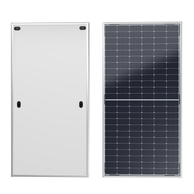
The current SOLETKS T/PV Pro product page publishes 336.3 W electrical output at a 48°C operating condition, 71% peak thermal efficiency, up to 88% combined instantaneous efficiency, dimensions of 1800 × 1080 × 48 mm, a mass of 38 kg and a 0.6 MPa pressure rating.
For higher electrical output and thermal peak in commercial or heat-pump-coupled projects, the PVT‑E Type module (580 W electrical, 1,180 W thermal peak, N‑type TOPCon cells, 0.6 MPa) is positioned for larger roof areas and pool/seasonal-storage applications.
The important procurement lesson is not the headline number. It is the test condition. A value at 48°C is not automatically an STC electrical rating, and a combined instantaneous efficiency is not annual useful yield. Before using these figures, request the underlying test report, efficiency curves, area basis and exact model revision, then reproduce the result in the project model.

EPC procurement checklist for a UK PVT tender
Use the five expandable steps below as a working tender checklist — from freezing the design basis through to measurable acceptance criteria.
1 Freeze the design basis
Site coordinates, postcode, elevation and weather file
Roof geometry, orientation, tilt, horizon and hourly shading
Structural capacity, wind/snow actions, fire strategy and access zones
Half-hourly or hourly electricity, DHW, space-heating, pool or process-heat loads
Design flow/return temperatures and minimum useful delivery temperature
Primary and backup heat sources, heat emitters and operating schedules
Energy-price, export and carbon assumptions, each with a date and sensitivity range
2 Demand a model-specific product submittal
Electrical and thermal datasheets with the same model code and revision
Full certificates, directory links and laboratory reports — not logo sheets
Thermal coefficients, curve equations, test flow, aperture/gross area and uncertainty
STC power, power tolerance, temperature coefficients and I–V curves
Maximum pressure, proof pressure, stagnation and operating-temperature limits
Pressure drop vs. flow, fluid volume, port details and approved glycol range
Materials in contact with the fluid and compatibility with water chemistry
Dimensions, mass, centre of gravity, lifting points and mounting-zone drawing
Wind/snow/fire evidence for the proposed mounting arrangement
Product, performance, corrosion and labour warranty terms, including exclusions
3 Require a reproducible energy model
Require native model files or a transparent calculation workbook plus a PDF report. At minimum it should disclose:
Weather source and years; simulation time step
Collector coefficients and area basis; PV thermal model and inverter losses
Pipe, heat-exchanger and store losses; pump and control electricity
Heat rejected or unavailable; heat-pump performance map, not one nominal COP
Backup-energy use; monthly electricity, available heat, useful heat and unmet load
Test at least low-, central- and high-use cases. A yield guarantee based only on the central case is not a robust guarantee.
4 Write the control sequence before purchase
When each pump starts and stops; which sensor has priority
How the system chooses between PVT, ground, air, storage and backup sources
Minimum/maximum collector, source and store temperatures
Freeze, stagnation, over-pressure, low-flow and sensor-failure responses
Minimum heat-pump run time and anti-cycling logic; power-loss behaviour
Which alarms are visible remotely and retained in the trend log
5 Use measurable acceptance criteria
Do not accept "system operational" as the only commissioning result. The handover test should verify:
Electrical insulation, polarity, protection, inverter and meter operation
Hydraulic pressure, flow, flushing, air removal, glycol concentration and safety devices
Calibrated heat-meter and electricity-meter readings; sensor names, locations and plausibility
The complete source-switch and backup sequence; communication and alarm retention
Delivery of as-built drawings, settings, certificates, warranties and maintenance instructions
The 12-month measurement plan
A defensible PVT case study needs more than a dashboard screenshot. Trend at intervals short enough to diagnose cycling — typically 5 to 15 minutes — and retain the following:
| Meter / signal | Required KPI | Why it matters |
|---|---|---|
| PVT electrical meter | kWh_e and specific yield, kWh/kWp | Separates electricity from thermal claims and supports PV model comparison |
| PVT heat meter | Useful kWh_th, flow and ΔT | Shows heat actually transferred — not absorber peak power |
| PVT circulation pump | Pump kWh | Prevents parasitic electricity from disappearing from the energy balance |
| Heat-pump electricity + heat meter | COP by operating state, seasonal performance factor | Shows whether PVT improves the complete heat-pump system |
| Source, collector, store and ambient sensors | Temperature distributions and operating hours | Explains why performance changes; identifies control or storage constraints |
| Backup heat meter | kWh by fuel/source | Prevents the solar contribution from being overstated |
Report availability and missing-data periods. Compare measured results with the model using the measured weather and load where possible; otherwise the comparison confuses design error with a different operating year.
When PVT is — and is not — a strong UK choice
✔ PVT is compelling when…
Roof area is constrained, both energy streams have concurrent value, heat can be used at low temperature, and the team can integrate controls, storage and metering. Hotels, leisure centres, multi-residential hot-water systems, pools, and carefully designed heat-pump systems can meet these conditions — see also industrial energy systems and agricultural energy systems for process pre-heat use cases.
✘ Choose separate PV / thermal when…
The heat sink is small or seasonal, roof area is ample, the project cannot support hydraulic maintenance, or the tender cannot produce verifiable model-specific evidence. A standard flat-plate solar thermal collector plus separate PV — or PV alone with another heat source — may be the safer route. Technology selection should follow the load, not the combined-efficiency headline.
Frequently asked questions
Do PVT panels work in the UK?
Yes, but "work" is not the same as meeting the full annual heating load. UK irradiance can support useful electricity and low-temperature heat, particularly where domestic hot water, pools, process pre-heating or a heat pump can absorb it. Winter peak heat still needs a dependable design source. Model the exact site, temperature level, storage and load profile.
Are PVT panels covered by MCS?
MCS 004 defines PVT collectors within the solar-heating product standard, but buyers must verify the exact model's current directory entry and evidence. A certificate for another collector, a company-level logo, or a PV-only certificate is not enough. Installation requirements also involve the applicable solar-heating, PV, roof-fixing and electrical standards.
Will PVT improve a UK Energy Performance Certificate?
It may improve modelled renewable-electricity and solar-heat inputs, but the credited result depends on the approved methodology, software, product data and project route. SAP 10.3 does not publish a separate named PVT category. Ask the accredited assessor to document how both outputs are entered and checked against double counting before procurement.
Can PVT be the only source for a heat pump?
Only in a purpose-designed system whose collector and heat pump are validated across no-sun, low-temperature, icing and peak-load conditions. For many projects, PVT is safer as an auxiliary source, ground-loop regenerator or pre-heater while a conventional source and backup strategy remain available. Never size winter capacity from peak solar output alone.
What should an EPC buyer request first from a PVT supplier?
Start with the exact model codes, electrical and thermal test reports, live certificate or directory records, efficiency curves, pressure-drop data, material and glycol limits, mounting evidence and warranty wording. Then request a reproducible hourly model and control narrative. A quotation without this evidence should remain technically non-compliant until the gaps are closed.
Build the evidence package before the quotation becomes a guarantee
Send SOLETKS your site location, roof drawing, hourly electricity and heat loads, target temperatures, heat-pump model, storage concept and required UK compliance route. Our engineering response will identify both the proposed configuration and the evidence still required before tender.
Request a Project-Based PVT Assessment →Sources
UK Department for Business, Energy & Industrial Strategy, Evidence gathering: Hybrid solar photovoltaic thermal panels (PVT), 16 November 2016.
MCS, MCS 004 Issue 4.0: Solar Heating Products, 1 August 2024.
MCS, MIS 3001 Issue 5.1: Solar Heating Systems, 17 April 2025.
MCS, MIS 3002:2025 Issue 2.0: Solar PV Installation, 18 March 2026.
UK Government, Standard Assessment Procedure — current methodologies and HEM status, updated 8 June 2026.
BRE, SAP 10.3 full specification, 12 June 2026.
European Commission Joint Research Centre, PVGIS API non-interactive service.
IEA Solar Heating and Cooling Task 60, Performance Assessment of Example PVT Systems, December 2020.
MCS, MCS 005 Issue 4.0: Photovoltaic Modules, 1 August 2024.
ISO, ISO 9806:2025 — Solar thermal collectors: Test methods, 2025.
MCS, MIS 3005-D Issue 3.0: Heat Pump Design Standard, 5 December 2025.
SOLETKS, T/PV Pro photovoltaic-thermal hybrid module, accessed 1 September 2026.
SOLETKS, How to Configure a PVT System: Six PVT and Heat-Pump Layouts, accessed 1 September 2026.