Chinese
 Español
 Francés
 Deutsch
 Русский
 العربية
 Português
 日本語
 한국어
 Italiano

Heat Pipe Technology Solar Water Heater
Heat Pipe Technology Solar Water Heater
Sealed copper heat pipes inside evacuated tubes move solar heat by phase change — without circulating potable water through every tube. Here is how it works, how to size it, and the freeze/pressure limits that decide the project.
Short Answer
Quick Verdict
A heat pipe technology solar water heater uses sealed copper heat pipes inside evacuated glass tubes to move solar heat into a manifold — without circulating potable water through every tube. Solar radiation heats the evaporator section of each pipe; the working fluid vaporises, rises to the condenser bulb, releases heat to the manifold loop, condenses, and returns to the evaporator by gravity. The Soletks HPC series completes that cycle in roughly 5 seconds from first sun exposure and operates with a rated 0.6 MPa working pressure and 120 °C maximum operating temperature.
This design is useful when the buyer wants evacuated-tube cold-weather performance, pressurised manifold heat transfer, and easier tube service than a direct water-in-glass system. It is not the right answer for every project: flat plate collectors remain simpler for many warm-climate hotel and dormitory systems, while heat pipe collectors become more attractive when winter performance, modular tube replacement, or higher temperature lift matters.
For Soletks product paths, use the evacuated tube solar collector category, the heat pipe solar collector page (HPC series), the heat pipe solar collector technical guide, and the cold-climate / winter performance guide. Sizing inquiries can be submitted through the Soletks contact page.
 HPC evidence
Model scope before mechanism claims
The heat-pipe explanation should be backed by certificate scope for the evacuated-tube product family.
This document does not replace the thermal performance curve, but it gives procurement teams a clean first check: product family, ISO reference, certificate number and expiry date.
How the Heat Pipe Works
The heat pipe transfers heat by phase change, not by pumping water through the glass tube. The sealed copper pipe contains a small amount of working fluid under controlled vacuum pressure. When sunlight heats the absorber fin (Soletks HPC uses 3003 anti-rust aluminium fins, 0.2 mm wall, 1620 mm long, bonded onto a copper heat pipe inside a Φ58 × 1800 mm vacuum tube), the working fluid evaporates. Vapour rises to the condenser bulb seated in the manifold pocket, releases latent heat to the manifold water or glycol loop, and condenses back into liquid.
The four-step phase-change cycle
Evaporate
Sun heats the absorber fin; working fluid in the heated end vaporises.
Rise
Vapour rises to the condenser bulb seated in the manifold pocket.
Release
Latent heat transfers to the manifold water/glycol loop; vapour condenses.
Return
Condensed liquid drains back to the evaporator by gravity — cycle repeats.
This phase-change mechanism matters for three reasons. First, latent heat transport moves large amounts of energy across a small temperature difference — Soletks reports overall thermal conductivity along the pipe up to 99% and a heat-transfer response time of about 5 seconds after first solar exposure. Second, it isolates the tube interior from the system fluid in the manifold, so a broken glass tube does not open the entire water loop to atmosphere. Third, the design behaves as a thermal diode: heat moves easily upward to the manifold but reverse heat loss at night is naturally suppressed.
Gravity return is the constraint. Condensed working fluid must drain back to the heated end before the next evaporation cycle begins, which is why heat pipe collectors require a minimum installation tilt (commonly 20°–25° at the lower bound, up to roughly 70° at the upper bound — the supplier's installation manual is the binding reference).[1]
| Heat pipe section | Function | Buyer question |
|---|---|---|
| Evaporator section (in vacuum tube) | Absorbs solar heat through the absorber fin | What absorber and fin material are used? |
| Condenser bulb (in manifold) | Releases heat to the manifold fluid | What contact area and dry/wet connection is used? |
| Working fluid | Evaporates and condenses in a closed loop | What operating temperature range is rated? |
| Manifold socket | Conducts heat into the water or glycol loop | How is thermal contact pressure maintained? |
| Gravity return path | Returns condensed liquid to evaporator | What minimum tilt angle is required? |
Sizing Example
A heat pipe solar water heater should be sized from daily hot water demand first — then translated into tube count, never the other way around. The screening formula below uses standard water properties (cp ≈ 4.186 kJ/(kg·K), ρ ≈ 1 kg/L). Dividing by 3600 gives the convenient constant 0.001163 kWh per (L·K).[1]
Daily heat demand (kWh/day)
  = Daily volume (L) × Temperature rise (K) × 0.001163

Derivation:
  0.001163 ≈ (1 kg/L × 4.186 kJ/(kg·K)) ÷ 3600 s/h
           ≈ 4.186 kJ/(L·K) ÷ 3600
           ≈ 0.001163 kWh / (L·K)
| Input | Value |
|---|---|
| Daily hot water demand | 200 L/day |
| Cold water inlet | 10 °C |
| Target hot water | 55 °C |
| Temperature rise (ΔT) | 45 K |
| Useful heat demand | 10.47 kWh/day |
| Desired solar fraction | 60% |
| Solar heat target | 6.28 kWh/day |
| Useful collector yield (screening) | 2.0 kWh/m²/day |
| Required aperture (screening) | 3.14 m² |
Cross-checking against the Soletks HPC series aperture areas, a 3.14 m² lighting area sits between the HPC298 (2.0 m²) and HPC370 (2.5 m²) modules — meaning a single HPC442 (3.0 m² lighting area) or a pair of HPC240 (2 × 1.6 = 3.2 m²) both land in the right zone. The recommendation is therefore to start at 3–5 m² of aperture and then refine by climate, target temperature, tube model, manifold loss, and backup heater strategy.[1]
This calculation prevents the most common buyer mistake: buying by the number of tubes before defining the daily load.
Heat Pipe vs Other Options
Heat pipe technology is strongest when the buyer needs evacuated-tube performance with a serviceable, pressurised manifold. The matrix below is a screening comparison; final selection depends on climate, target temperature, pressure, maintenance access, and local codes.[1]
| Option | Best temp range | Service life / inspection | Best fit | Limitation |
|---|---|---|---|---|
| Flat plate collector | 35–70 °C | 15–25 yr; annual | Hotels, dormitories, warm climates | Higher loss in cold wind |
| Heat pipe evacuated tube (HPC) | 45–85 °C | 15+ yr; annual | Cold climates, higher lift, modular tube service | Min. tilt & condenser contact matter |
| U-tube evacuated collector | 45–90 °C | 10–20 yr; annual | Closed-loop commercial systems | More installation discipline |
| Direct water-in-glass tube | 35–70 °C | 5–15 yr; seasonal | Low-cost non-pressurised residential | Freeze and pressure limits |
| PVT hybrid panel | 25–55 °C + power | 15–25 yr; annual | Roof-limited dual-energy projects | Not first choice for heat-only |
The cause-and-effect decision is straightforward: evacuated tubes reduce convective heat loss because the vacuum eliminates air movement around the absorber — Soletks HPC tubes report a total heat-loss coefficient of 2.453 W/(m²·K) under standard test conditions. Heat pipes add a serviceable phase-change transfer path with a thermal-diode behaviour, but they also add a minimum-tilt requirement and a dry-contact thermal interface that must be specified properly.
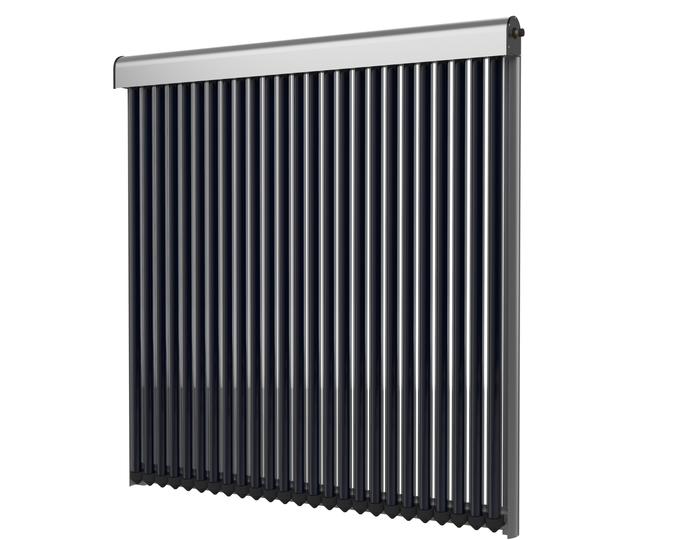
Transfer path comparison
U-tube and heat-pipe collectors share vacuum insulation, but the service logic is different.
The heat pipe adds a serviceable thermal-diode phase-change path and a minimum-tilt requirement, while U-tube systems depend on closed-loop installation discipline.
Freeze and Pressure Boundaries
Heat pipe tubes improve cold-weather resilience, but the system still needs freeze and pressure design. The vacuum tube may not contain bulk water, but the manifold, piping, pump station, and storage tank still hold fluid that can freeze, expand, or over-pressurise. The Soletks HPC series is rated for −50 °C to +40 °C ambient and 0.6 MPa working pressure, but those numbers only describe the collector — the rest of the loop has to be designed to match.[1]
Common mistake: assuming a "dry" heat pipe tube makes the whole system freeze-proof. It does not. Exposed manifold piping, the pump station and the tank still freeze — design a closed glycol loop or drainback for the balance of system.
| Design item | Practical rule | Why it matters |
|---|---|---|
| Minimum tilt | Follow supplier minimum (commonly ≥ 20°–25°) | Heat pipe condensate must return by gravity |
| Manifold loop in freezing climates | Closed glycol loop or drainback | Exposed piping freezes even when tubes are dry |
| Working pressure | Match collector and tank ratings (HPC: 0.6 MPa) | Pressurised systems need explicit safety margin |
| Expansion volume | Sized for stagnation and fluid thermal expansion | Protects valves, manifold, and pump station |
| Stagnation strategy | Controller + pressure relief + steam-back design | Protects glycol from thermal degradation |
| Backup heat | Keep full peak-load backup capacity | Solar yield falls during storms and night |
| Tube service | Specify spare tubes and replacement procedure | Reduces downtime after breakage |
For freezing-climate projects, the buyer should compare heat pipe collectors with closed glycol-loop or drainback designs rather than assuming the dry tube alone solves every winter risk. The detailed trade-off is covered in the Soletks cold-climate solar water heater guide.
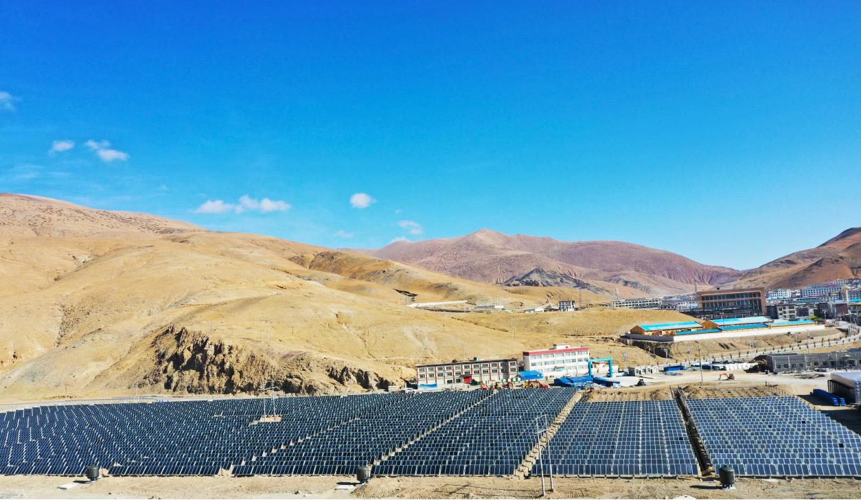
Cold-climate field context
High altitude is where the freeze and pressure boundaries become the design story.
This field reference now supports the surrounding paragraph: evacuated heat-pipe tubes help, but the whole loop still needs glycol, drainback, expansion and pressure protection.
Soletks HPC Series Reference Data
Real product nameplates make the heat pipe technology auditable. The Soletks HPC ("Heat Pipe Collector") series uses a uniform vacuum tube (Φ58 × 1800 mm, 2.0 mm outer / 1.6 mm inner wall) and a uniform copper heat pipe with 3003 aluminium fin (0.2 mm thick, 1620 mm long), so the only project-level variable is how many tubes the collector carries.
| Model | Tubes | Gross area | Aperture area | Net weight | Rated @ 1000 W/m² | Volume |
|---|---|---|---|---|---|---|
| HPC182 | 12 | 1.82 m² | 1.2 m² | 42 kg | 0.72 kW | 0.80 L |
| HPC240 | 16 | 2.40 m² | 1.6 m² | 55 kg | 0.96 kW | 1.04 L |
| HPC298 | 20 | 2.98 m² | 2.0 m² | 67 kg | 1.20 kW | 1.27 L |
| HPC370 | 25 | 3.70 m² | 2.5 m² | 85 kg | 1.50 kW | 1.57 L |
| HPC442 | 30 | 4.42 m² | 3.0 m² | 99 kg | 1.80 kW | 1.86 L |
Common parameters across the series: peak efficiency 0.724, rated efficiency 0.6, total heat loss coefficient 2.453 W/(m²·K), working pressure 0.6 MPa, maximum operating temperature 120 °C, ambient working range −50 °C to +40 °C, two manifold interfaces with 22 mm light-tube outlets. Winter heat-exchange efficiency remains above 55% in field operation thanks to the phase-change response time of about 5 seconds.
Cross-checking the sizing example earlier: at the rated 1000 W/m² point, an HPC442 delivers 1.80 kW of thermal power, so 4 peak-equivalent hours yield about 7.2 kWh/day — which covers the 6.28 kWh/day solar target with margin for piping and manifold losses, and confirms that a single HPC442 is a clean fit for a 200 L/day villa at 60% solar fraction.
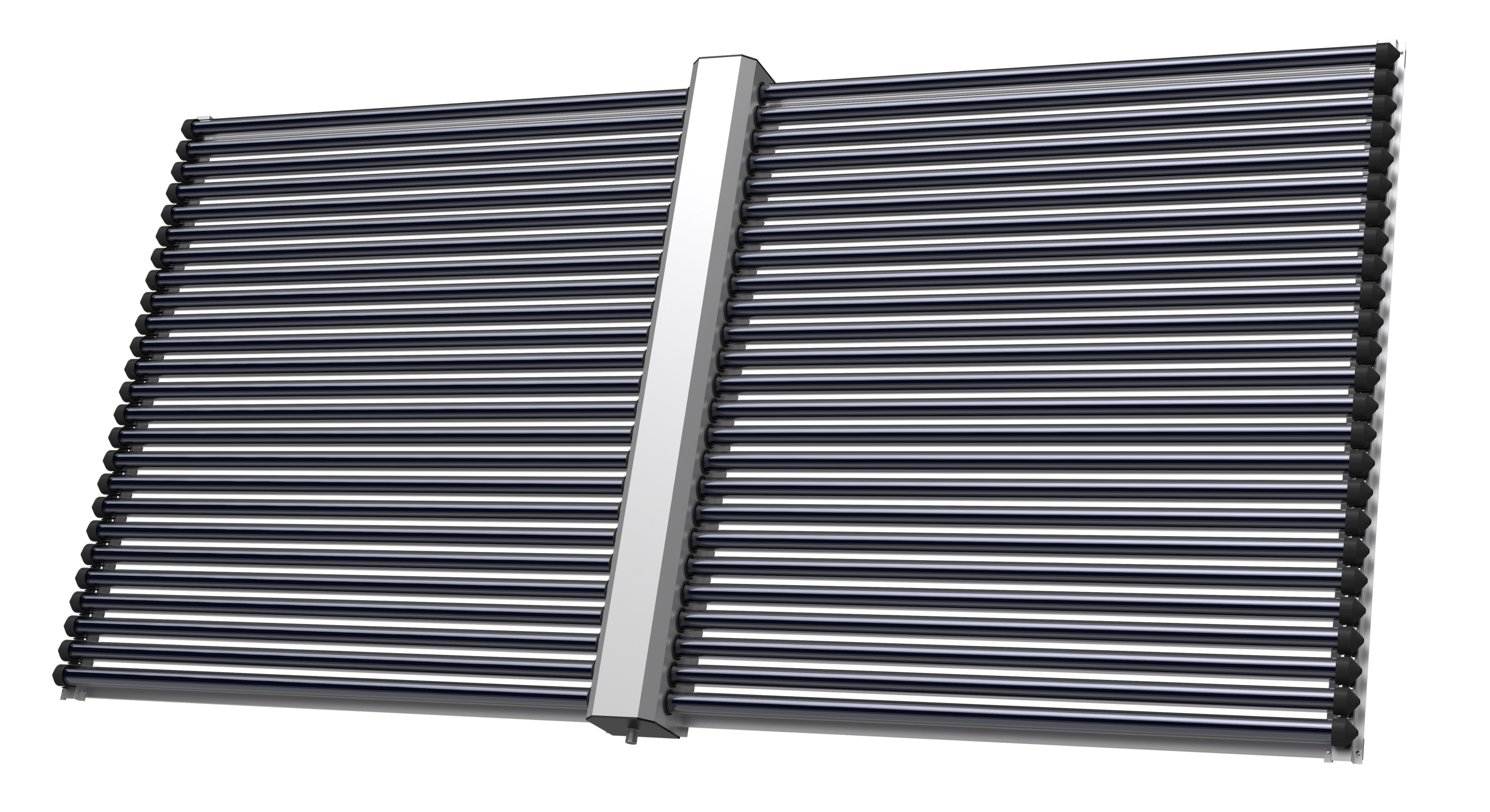
Auditable hardware reference
Put the collector image beside the nameplate variables buyers actually compare.
The important point is not a huge product photo; it is the uniform tube platform, copper heat pipe, aluminium fin and tube-count choice across HPC models.
Standards and Documents to Request
A heat pipe solar water heater proposal should document collector testing, pressure boundaries, and fluid compatibility — not just a glossy brochure.
| Standard or document | Applies to | Buyer action |
|---|---|---|
| ISO 9806:2017 | Solar collector performance testing (incl. evacuated tube & heat pipe) | Request thermal data referenced to ISO 9806 |
| EN 12975 | Legacy European reference for solar thermal collectors | Use when older tenders still name EN 12975 |
| EN 12976 | Factory-made solar thermal system reference | Use for packaged-system tender language |
| Solar Keymark | European certification scheme based on EN/ISO standards | Match incentive or tender requirement |
| NSF/ANSI 61 | Drinking-water contact materials | Apply when potable components contact drinking water |
| ASTM D3306 | Glycol-based coolant reference | Cross-reference for indirect glycol loops (ASTM D3306) |
| ASME BPVC Section VIII | Pressure vessel reference | Apply when tank/HX rules require code stamping |
| ISO 9001 | Quality management system | Request factory quality documentation in tenders |
For collector test references, buyers should anchor the RFQ to ISO 9806, which explicitly covers heat pipe evacuated tube collectors. Solar Keymark is the practical European certification umbrella that consumes the ISO/EN test results. Pressure vessel and potable-water standards apply to the balance of system, not to the collector itself.
When to Choose Heat Pipe Technology
Choose heat pipe technology when the project benefits from evacuated-tube heat retention and the maintenance team values modular tube service.
The good-fit conditions are when winter or shoulder-season performance matters, target hot water is often above 55 °C, the system is pressurised through a manifold (not direct tube water storage), tube replacement access is practical, the project accepts the supplier's minimum tilt angle, and the supplier provides collector test data, pressure limits, and a complete installation manual.
In a representative Soletks heat pipe project discussion, the buyer specified 200 L/day villa hot water demand, a winter inlet near 10 °C, a target tank temperature of 55 °C, and a winter design ambient of about −15 °C. The 10.47 kWh/day load calculation pointed directly at a single HPC442 collector (3.0 m² aperture, 1.8 kW rated) paired with a glycol closed loop and a 5 kW electric backup heater — a far more useful conversation than the buyer's original request for "give me a quote for 20 tubes."[1]
RFQ Inputs for Soletks
A heat pipe RFQ should state the load, climate, and pressure requirements before asking for tube count.
Include the following in your inquiry
For engineering support, send the RFQ data through the Soletks contact page and request a heat pipe solar water heater sizing analysis. A useful reply should show heat demand in kWh/day, collector aperture in m², HPC model and quantity, manifold design, freeze protection method, and backup heater sizing — all in the same table.
Specification Checklist
| Specification item | Minimum value to include | Why it matters |
|---|---|---|
| Tube size and quantity | Diameter, length, and tube count | Defines aperture and spare-part stocking |
| Manifold rating | Working pressure (MPa) and test pressure | Protects pressurised operation |
| Heat pipe rating | Operating temperature range | Prevents mismatch with climate and target heat |
| Tilt requirement | Minimum degrees | Ensures condensate gravity return |
| Collector test data | ISO 9806 results, η₀ and heat-loss coefficient | Supports yield comparison |
| Freeze protection | Glycol, drainback, or other method | Protects manifold and piping |
| Stagnation strategy | Expansion vessel size and control method | Protects loop under no-load sun |
| Backup heater | kW and fuel type | Covers cloudy days and night load |
| Warranty | Years and exclusions | Clarifies tube, manifold, and labour responsibility |
| Documents | Datasheet, drawing, manual, packing list | Supports procurement and installation |
Quick Calculator
Three lines to estimate daily heat demand for any solar water heater RFQ:
Step 1   Read or specify:  V (L/day), T_cold (°C), T_target (°C)
Step 2   ΔT = T_target − T_cold
Step 3   Daily heat (kWh) = V × ΔT × 0.001163
Worked check for a 300 L/day small hotel application at 15 °C → 60 °C: 300 × 45 × 0.001163 ≈ 15.7 kWh/day. At 60% solar fraction and 2.2 kWh/m²/day useful yield, that points to roughly 4.3 m² of aperture — i.e. an HPC442 plus an HPC182, or two HPC298 modules. If a supplier's recommended tube count cannot be reverse-checked with this formula within ±15%, ask for the assumed solar fraction and irradiation in writing.
Size the load before counting tubes
Send daily volume, inlet/target temperature, winter design ambient and roof tilt. Soletks returns heat demand, aperture, HPC model/quantity, freeze design and backup sizing in one table.
FAQ
Q1.What is heat pipe technology in a solar water heater?
Q2.Is a heat pipe solar water heater good for winter?
Q3.How do I size a heat pipe solar water heater?
Q4.Is heat pipe better than flat plate?
Q5.What is the minimum installation tilt for a heat pipe collector?
Q6.What information does Soletks need for a quotation?
Key Takeaways
Remember these five
A heat pipe solar water heater transfers heat by phase change, not by pumping water through the tubes — which is why a broken vacuum tube does not open the whole water loop.
Always size from daily hot water demand first using V × ΔT × 0.001163, then translate kWh/day into aperture area and finally into HPC model and quantity.
The Soletks HPC series spans 1.2–3.0 m² aperture with uniform 0.6 MPa pressure, 120 °C max temperature, 2.453 W/(m²·K) heat loss coefficient, and 0.724 peak efficiency — so the only real model decision is how much aperture the load needs.
Cold-climate winter resilience requires freeze protection on the whole loop, not just dry tubes — usually a glycol closed loop or a drainback design.
Anchor every RFQ to ISO 9806 test data and a minimum-tilt statement. If a supplier cannot produce both, the proposal is not auditable.
Sources
Authority references used in this article include ISO 9806:2017 solar collector performance testing (the binding reference for heat pipe evacuated tube collectors), EN 12975 and EN 12976 legacy and packaged-system references, Solar Keymark certification scheme, NSF/ANSI 61 for potable-water contact materials, ASTM D3306 for glycol coolant cross-reference, ASME BPVC Section VIII for pressure vessel rules, and ISO 9001 for quality management. Soletks HPC182, HPC240, HPC298, HPC370, and HPC442 nameplate values (0.6 MPa working pressure, 120 °C maximum operating temperature, 2.453 W/(m²·K) heat loss coefficient, 0.724 peak efficiency, 5-second phase-change response, −50 °C to +40 °C ambient range) are taken from the manufacturer's product pages linked in the body of this article.
Screening formulas and service ranges in this article are for early engineering comparison. The 0.001163 constant is derived as (1 kg/L × 4.186 kJ/(kg·K)) ÷ 3600 ≈ 0.001163 kWh/(L·K). Final values should use current Soletks datasheets, certified ISO 9806 test data, local irradiation, project layout, working-pressure requirements, and installation conditions.