Chinese
 Español
 Francés
 Deutsch
 Русский
 العربية
 Português
 日本語
 한국어
 Italiano

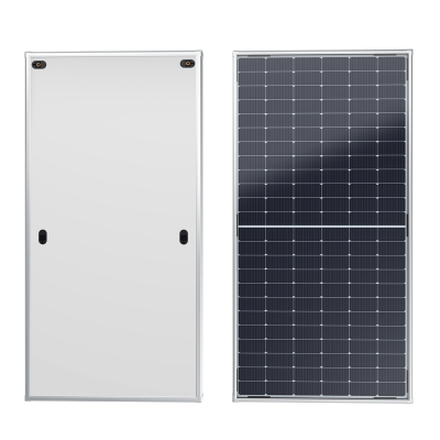
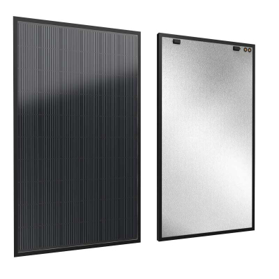
Flat Plate Collector Components and Construction Diagram
Flat Plate Collector Components and Construction Diagram
Two datasheets can look identical — same aperture, same pressure, both "selective coating" — yet differ 15–25% in field yield. The difference hides in the absorber bond, the coating process and the insulation density. Here's the collector, layer by layer.
Why Two "Identical" Collectors Behave Differently
A procurement manager compares two datasheets that look almost identical: same aperture, same 0.6 MPa rating, both "selective coating", both "low-iron tempered glass". One supplier quotes 15% lower. Three years after installation, the cheap collectors produce 18% less heat in the same field. The difference was never on the headline — it was in the absorber-to-tube bonding (mechanical clip vs. laser weld), the coating process (sputtered selective paint vs. PVD), and the insulation density (60 vs 100 kg/m³). This guide opens the collector layer by layer.
Key Takeaways
The four hidden differentiators
The four highest-impact components are the absorber coating (PVD α=95% / ε=5% vs. lower-grade), the absorber-to-tube bond (laser weld vs. ultrasonic vs. mechanical), the glazing (low-iron >92% vs. standard ~88%), and the insulation density (high-density PU vs. cheap mineral wool).
Together these four can swing annual yield by 15–25% between two collectors with the same aperture and same nominal pressure rating.
Working pressure separates residential collectors (0.6 MPa, e.g. BTE-2.0-2) from district-heating-grade collectors (1.0 MPa, e.g. EFPC150).
The construction diagram should be read glass-down: glazing → air gap → coating → absorber sheet → tubes → insulation → frame and backsheet. Each layer addresses a different loss mechanism.
A 2.0 m² collector at 800 W/m² and 65% efficiency produces 1.04 kW — the same 2.0 m² at Soletks 0.81 peak efficiency produces 1.30 kW, a 25% difference from coating and bonding quality alone.
TL;DR
Quick Verdict
Flat plate collector components are the glazing, absorber plate, selective coating, riser tubes, headers, insulation, frame, backsheet, seals and mounting interfaces. Buyers should compare each part because each one changes thermal output, corrosion resistance, service life, pressure rating and shipping durability. A datasheet that lists components without stating absorber-bond method, coating process (PVD vs. alternatives), glass transmittance and insulation density gives buyers no way to compare beyond price.
For a quick heat screen, a 2.0 m² collector at 800 W/m² and 65% efficiency produces about 1.04 kW. A premium collector at 0.81 peak efficiency (Soletks high-performance range with PVD coating) produces about 1.30 kW under the same conditions.
For Soletks paths, compare the flat plate solar collector category, the high-efficiency flat plate collector (PVD α=95% / ε=5% at 80 °C, 0.81 peak, low-iron glass >92%), the large-scale flat plate collector range (EFPC150: 15 m² gross, 13.92 m² aperture, 1.0 MPa, HTC40), the durable flat-plate collector selection guide, and the Soletks inquiry page.
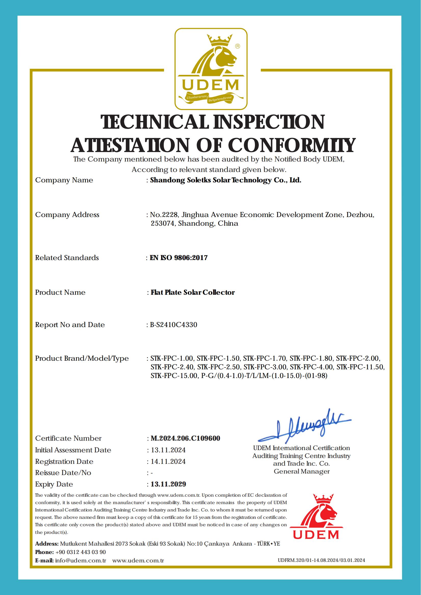 Component evidence
Documentation behind the layers
A component diagram is only useful when the supplier can prove the product family and test reference behind it.
This certificate supports the collector family and ISO reference. It should be reviewed together with the datasheet items below: glass, absorber coating, riser/header tubes, insulation, frame and pressure rating.
Construction Diagram Reading Order
A flat-plate collector should be read from the sun-facing glass down to the backsheet because heat gain and heat loss follow that path. The glazing admits solar radiation, the absorber converts it into heat, the tubes carry heat away, and insulation reduces loss from the rear and edges.
Each layer addresses a different loss mechanism. Glazing affects optical gain (5–10% swing). Coating affects radiation loss (ε=10% vs ε=5% costs ~5% of high-temperature yield). Bonding affects conduction into the fluid. Insulation affects rear loss. A weak link in any one layer ceilings the entire collector's performance, regardless of how good the other layers are.
Typical Component Dimensions Reference
| Component | Standard range | Premium range | Soletks reference |
|---|---|---|---|
| Glass thickness | 3.2 mm | 3.2–4.0 mm tempered low-iron | 3.2 mm low-iron, >92% transmittance |
| Glass transmittance | 88–90% | 91–93% | >92% (high-performance) |
| Absorber material | Al 0.3 mm or steel | Cu 0.2 mm or Al 0.4 mm | Aluminium + PVD coating (BTE-2.0); Cu available |
| Coating absorptance (α) | 90–93% | 94–96% | 95% ±2% (PVD) |
| Coating emittance (ε) @ 80 °C | 8–12% | 5–7% | 5% ±2% (PVD at 80 °C) |
| Riser tube | Cu Φ8×0.6, 10–12 risers | Cu Φ8×0.6, 12+, laser-welded | Laser-welded full-area flow channel |
| Header tube | Cu Φ22 mm | Cu Φ22–28 mm | Cu Φ22 mm, G3/4 quick connect |
| Insulation | Mineral wool 40 mm, ~60 kg/m³ | PU foam 40 mm, ≥80 kg/m³ | High-density PU, instant foaming |
| Frame | Aluminium, anodized | Aluminium S11 powder-coated | Aluminium S11 / metallic grey |
| Working pressure | 0.6 MPa residential | 1.0 MPa commercial | 0.6 MPa (BTE-2.0), 1.0 MPa (EFPC) |
The premium-range values correspond to measurable test outcomes. A 92% glass with a PVD α=95% / ε=5% absorber gives roughly 6–8 percentage points higher peak efficiency than a 88%-glass / α=93% / ε=10% standard build at the same aperture.
Absorber Coating: PVD vs Alternatives
The absorber's selective coating is the single component buyers most often under-spec. Two coatings can look identical (both black, both "selective") and differ by 5–10 percentage points of high-temperature efficiency.
| Coating type | α | ε @ 80 °C | Lifetime trend | Cost class |
|---|---|---|---|---|
| Black paint (non-selective) | 90–94% | 80–88% | Degrades fast above 100 °C | Lowest — pool only |
| Sputtered selective paint | 92–94% | 10–15% | OK below 130 °C stagnation | Low-mid |
| Sputtered black chrome | 92–95% | 7–12% | Good, slow drift 15+ yr | Mid |
| PVD blue-film | 94–96% | 5–7% | Excellent to 200 °C+ stagnation | Mid-high |
| Sputtered TiNOx-class | 95–96% | 4–6% | Top tier, very stable | High |
Soletks high-performance flat-plate collectors use a PVD-deposited blue-film coating with measured α = 95% ± 2% and ε = 5% ± 2% at 80 °C. The combination raises peak efficiency to 0.81 — measurably above the 0.70–0.74 typical of standard sputtered-paint products. For subsidy programs or Solar Keymark certification, PVD coatings have an easier qualification path because their test repeatability is higher.
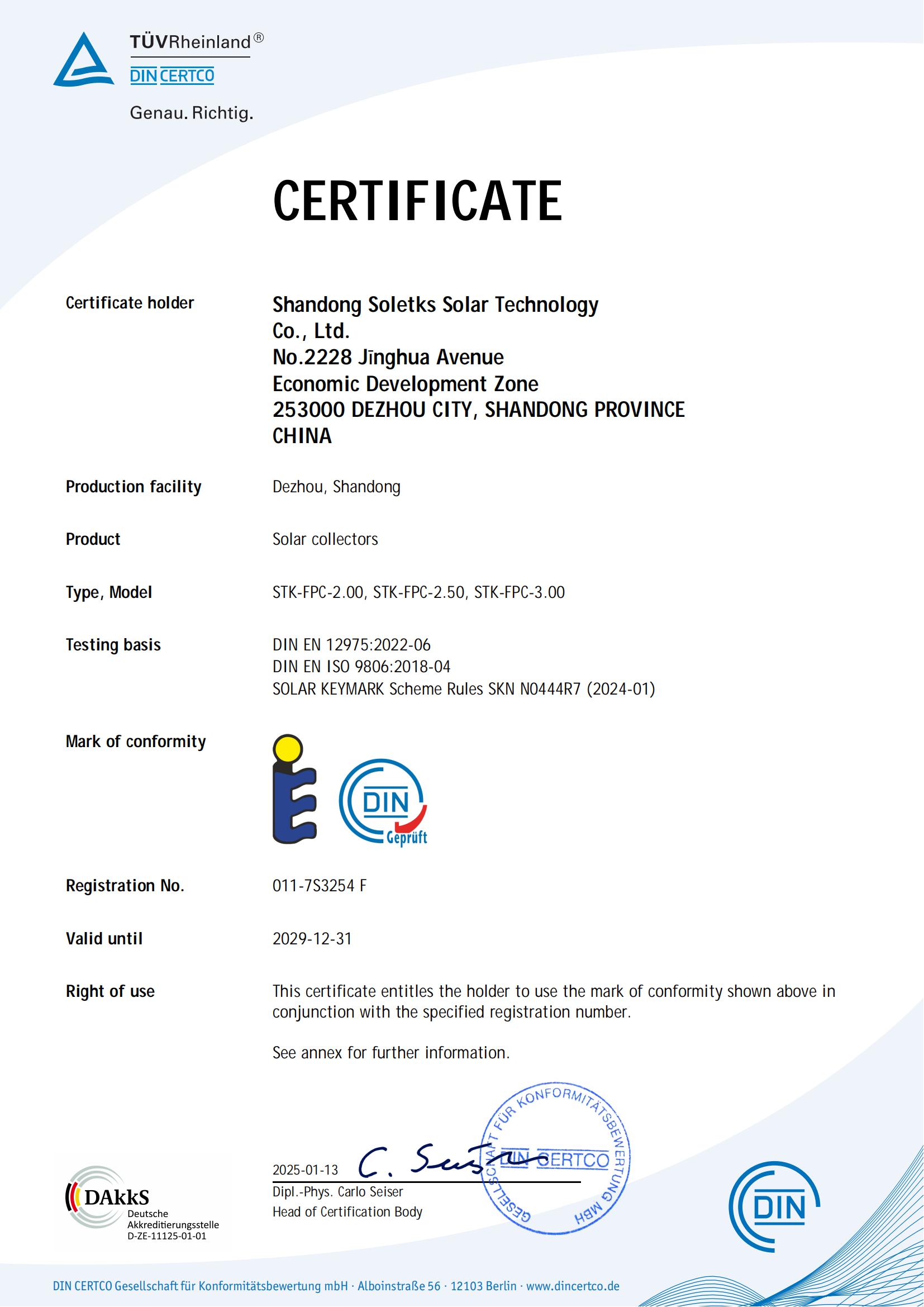 Solar Keymark
Coating claims need test documents
Solar Keymark turns coating and performance claims into a document buyers can audit.
PVD coating claims should be tied to certificate scope and collector test data. For EU projects, match the registration number and model list before accepting absorptance and emittance claims.
Absorber-to-Tube Bond: Laser vs Ultrasonic vs Mechanical
The way the absorber sheet meets the riser tubes is the second-biggest hidden differentiator. Heat must move from a broad sheet into a narrow fluid path; a weak bond creates thermal resistance and hot spots.
| Bond method | Heat-transfer quality | Stagnation tolerance | Cost |
|---|---|---|---|
| Mechanical clip / press-fit | Lowest — air gap at bond line | Poor; coating may delaminate | Lowest |
| Mechanical with thermal paste | Low–medium; paste degrades | OK short-term, drifts down | Low |
| Ultrasonic weld (point welds) | Medium | OK for moderate stagnation | Mid |
| Laser weld (continuous seam) | Highest — metallurgical continuity | Excellent, stable to 200+ °C | Mid-high |
| Roll-bond aluminium (single-piece) | Highest in plane | Excellent | High |
Soletks high-performance flat-plate collectors use a fourth-generation full-area flow-channel structure with laser-welded continuous-seam bonding. The metallurgical bond eliminates the contact-resistance penalty that mechanically-clipped collectors carry. Over a 20-year service life, this translates into thousands of additional useful kWh per panel — far larger than the per-panel cost difference between mechanical and laser-welded production.
Heat Output Calculation — Standard vs Premium
Useful heat = aperture × irradiance × instantaneous efficiency

Standard: 2.0 × 800 × 0.65 = 1,040 W (1.04 kW)  → ×5 h = 5.2 kWh/day
Premium:  2.0 × 800 × 0.81 = 1,296 W (1.30 kW)  → ×5 h = 6.5 kWh/day
Difference per panel: +1.3 kWh/day (+25%)
| Input | Standard collector | Premium (Soletks high-performance) |
|---|---|---|
| Gross area | 2.0 m² | 2.0 m² |
| Aperture area | 1.87 m² | 1.9 m² |
| Solar irradiance | 800 W/m² | 800 W/m² |
| Instantaneous efficiency | 65% | 81% (peak) |
| Useful heat output | 1.04 kW | 1.30 kW |
| 5 useful sun hours | 5.2 kWh/day | 6.5 kWh/day |
| Difference per panel/day | — | +1.3 kWh/day (+25%) |
Over a 20-year service life, a 1.3 kWh/day delivered-heat difference per panel accumulates to roughly 9,500 kWh per panel — a number that dwarfs the per-panel premium for PVD coating and laser-welded bonding. This is why component quality is not "nice to have" but a major lifecycle economic factor.
Field example. A Soletks RFQ specified 2.0 m² target panels, an 8 bar (0.8 MPa) requirement, and a coastal installation within 5 km of the sea. The recommendation was the high-performance series (PVD α=95%/ε=5%, 0.81 peak) with the 1.0 MPa pressure margin and ASTM B117 salt-spray-validated S11 aluminium frame — not the standard 0.6 MPa BTE-2.0-2, even though both met the nominal 8 bar requirement on paper. Pressure margin and corrosion class were decided by component spec, not by the headline efficiency.
Component-by-Component Buyer Checks
The most important flat plate collector components are the absorber, tube bond, insulation and casing seal. These four parts decide whether the collector keeps output and stays dry after years of thermal cycling. A brochure that says "selective coating" or "copper tube" is not specific enough; the RFQ should ask for the measurable parameter behind each component.
| Component | What it does | Measurable RFQ item | Failure risk |
|---|---|---|---|
| Glazing | Admits solar radiation and blocks weather | 3.2-4.0 mm tempered low-iron glass, transmittance % | Hail breakage and edge-seal leakage |
| Selective coating | Absorbs sunlight and suppresses radiation loss | α and ε at 80 °C, PVD preferred | Output drop after stagnation events |
| Absorber plate | Spreads heat from coating into tubes | Cu or Al material and thickness | Poor heat transfer and hot spots |
| Tube bond | Couples absorber heat into the fluid path | Laser weld vs ultrasonic vs mechanical clip | Hot spots, contact loss and coating delamination |
| Riser tubes | Move heat-transfer fluid through the absorber | Diameter, wall thickness and spacing | Pressure loss or internal corrosion |
| Headers | Distribute flow across risers | Diameter, pressure rating and connector type | Uneven flow and joint leakage |
| Insulation | Reduces rear and edge heat loss | Material, density and 30-60 mm thickness | Wet insulation and accelerated heat loss |
| Frame and seals | Hold glass, absorber and backsheet aligned | Alloy, gasket type and drainage detail | Moisture ingress and frame corrosion |
Each of these items has a measurable value that can be written into a purchase specification. Once the buyer asks for those values, two collectors with the same aperture are no longer interchangeable. The comparison changes from "which panel is cheaper?" to "which collector keeps the certified output, pressure rating and weather seal for the next 15 to 25 years?"
Materials and Lifecycle Matrix
Material choices change collector service life, maintenance interval and lifecycle cost. The lowest first cost is rarely the lowest total cost once corrosion, stagnation and shipping damage are counted. A collector expands and contracts every day; weak seals admit moisture into insulation, wet insulation raises heat loss, and higher heat loss reduces delivered kWh even when the absorber still looks intact.
| Component option | Typical service life | Lifecycle cost driver | Stronger use condition |
|---|---|---|---|
| Tempered low-iron glass | 20-25 years; annual visual inspection | Breakage and edge-seal integrity | Standard rooftops and hail-risk sites |
| PVD selective coating | 20-25 years; annual inspection | Stability under stagnation cycles | Commercial fields and high summer stagnation |
| Sputtered paint selective coating | 12-18 years | Gradual α drift and ε creep at high temperature | Mild climates and lower-cost residential builds |
| Copper riser/header, laser-welded | 20-25 years; annual inspection | Copper price and corrosion control | Glycol loops, potable loops and premium projects |
| Aluminium absorber plus Cu tubes | 15-20 years; annual inspection | Bond quality and galvanic control | Cost-sensitive residential projects |
| High-density PU foam insulation | 20+ years; annual moisture inspection | Stays dry and keeps heat-loss creep low | Premium collectors in all climates |
| Mineral wool insulation | 12-18 years | Wet insulation replacement | Budget builds with low condensation risk |
| Aluminium S11 powder-coated frame | 20-25 years | Coating and fastener corrosion | Coastal, high-UV and high-wind sites |
The PU-foam advantage over mineral wool is not only lower initial heat loss. PU does not soak up condensate in the same way over 15 years of thermal cycling, so the collector keeps closer to its original test performance. In a large field, that stability can matter more than a small difference in purchase price.
Standards and Test Documents
A flat plate collector buyer should request thermal performance, durability and factory-quality documents. A component diagram is useful only when the supplier can back it with test data: ISO 9806 (collector performance and durability testing), EN 12975 (legacy standard), Solar Keymark (European certification), ASTM B117 (salt-spray corrosion exposure — critical for coastal), ISO 9227 (corrosion in artificial atmospheres), ASTM D3306 (glycol coolant), ASME BPVC Section VIII / PED 2014/68/EU (pressure vessel rules), and ISO 9001. For PVD-coated collectors, also ask for the coating-line stability report.
For source documents, use ISO 9806, ASTM B117 and ISO 9227.
RFQ Inputs for Soletks
A useful flat plate collector RFQ describes area, pressure, materials, climate and installation layout. Without those five, no supplier can recommend between a residential BTE-2.0-2 and a commercial EFPC150 with confidence.
Include the following in your inquiry
Submit through the Soletks inquiry page and request a component-level collector comparison. A useful reply should compare absorber material, coating process (PVD vs alternatives), bonding method, insulation density, frame class, pressure rating and available test documents in one side-by-side table — not just bottom-line price.
Specification Checklist
| Specification item | Value to include |
|---|---|
| Gross & aperture area | m² for both |
| Glazing | Material, thickness (mm), tempering, transmittance % |
| Absorber material | Cu or Al, thickness (mm) |
| Selective coating | Process (PVD/sputtered/paint), α %, ε % at 80 °C |
| Riser/header material | Material, diameter, wall thickness |
| Bonding method | Laser weld / ultrasonic / mechanical |
| Insulation | Material, density (kg/m³), thickness (mm) |
| Frame & backsheet | Alloy class (S11), coating, drainage |
| Working pressure | bar or MPa (0.6 residential, 1.0 commercial) |
| Connector | Thread type and quick-connect option |
| Test documents | ISO 9806 report, pressure test, Keymark cert, warranty |
Compare collectors layer by layer, not by headline price
Send area, pressure, materials, climate and layout. Soletks returns a component-level comparison — coating process, bond method, insulation density, frame class and test documents — in one table.
FAQ
Q1.What are the main flat plate collector components?
Q2.Which flat plate collector component affects efficiency most?
Q3.What is a PVD selective coating and why does it matter?
Q4.What is the difference between laser-welded and ultrasonic-welded absorbers?
Q5.How do I read a flat plate collector diagram?
Q6.How much heat does a 2 m² flat plate collector produce?
Q7.What working pressure should a flat plate collector have?
Q8.What documents should I request before buying flat plate collectors?
Sources and Disclaimer
Authority references used in this article include ISO 9806 (solar collector performance and durability testing), EN 12975 (legacy collector reference), Solar Keymark (European certification), ASTM B117 (salt-spray corrosion exposure), ISO 9227 (corrosion tests in artificial atmospheres), ASTM D3306 (glycol coolant reference), ASME BPVC Section VIII (pressure-vessel design), PED 2014/68/EU and ISO 9001 (quality management). Product data are from Soletks published specifications: high-performance flat plate collector (PVD selective coating with absorptance 95% ± 2% and emittance 5% ± 2% at 80 °C, peak efficiency 0.81, low-iron tempered glass with transmittance >92%, aperture 1.9 m², G3/4 internal-thread connector, aluminium S11 frame); BTE-2.0-2 (gross 2.0 m², aperture 1.87 m², 0.6 MPa, 78% optical efficiency); EFPC150 (gross 15 m², aperture 13.92 m², 0.81 peak, 11.26 kW peak, 1.0 MPa, HTC40 quick connector, 150 °C max). The component-dimension ranges, coating bands, bonding comparisons and lifecycle ranges are early procurement screening values; final selection must use supplier datasheets, ISO 9806 test data, pressure requirements, local climate, water chemistry, mounting design and installer requirements.